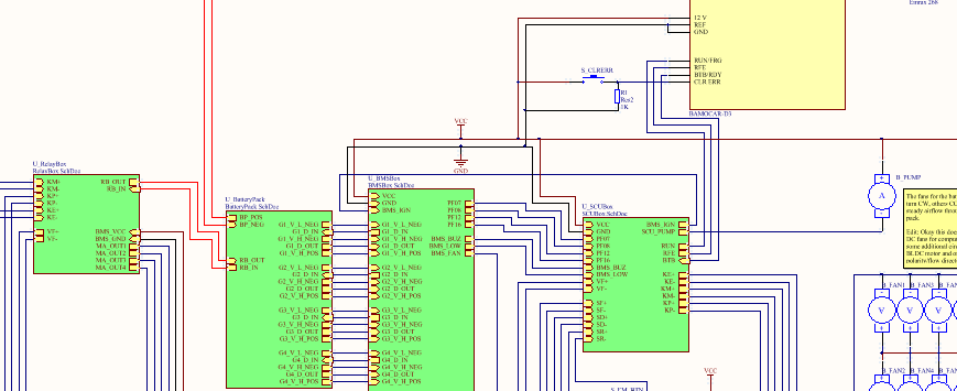
When finally all the subsystems of the electric bicycle were designed a new problem was knocking on our door. This problem is illustrated best with an example. Do you notice anything peculiar in the image below? No, nothing? I’ll tell you, all the subsystems are connected with lines. And although lines are perfect for a schematic overview, they will not do such a good job when it comes to conducting electric current in real life. This means that all those lines had to be replaced by cables with the right connectors attached, and all the wires had to be connected to the right pins inside those connectors. It is here that our adventure began through the jungle of different connectors to find the right ones, and to eventually install them on our motorcycle…
 Besides the high voltage DC+ and DC- connectors of the battery pack, it also needs some low voltage signals and power, for example to communicate with the Battery Management System and to switch the high voltage relays on and off. The BMS requires 10 pins and the relays and other high voltage safety measures require 8 pins. This is an ideal case for two LEMO plug/connector pairs of the IP68 variant. The other side of these cables will be connected to the BMS and our in-house designed Safety Control Unit (SCU).
LEMO provides connectors with different contact types. Some types make it possible to directly solder wires on the solder contacts of each pin, but other types are through hole technology (THT) for mounting on a PCB. The latter also proved useful on the PCB of the previously mentioned SCU, so the connector has direct connections with the functionality of this low-level safety unit.
Besides the high voltage DC+ and DC- connectors of the battery pack, it also needs some low voltage signals and power, for example to communicate with the Battery Management System and to switch the high voltage relays on and off. The BMS requires 10 pins and the relays and other high voltage safety measures require 8 pins. This is an ideal case for two LEMO plug/connector pairs of the IP68 variant. The other side of these cables will be connected to the BMS and our in-house designed Safety Control Unit (SCU).
LEMO provides connectors with different contact types. Some types make it possible to directly solder wires on the solder contacts of each pin, but other types are through hole technology (THT) for mounting on a PCB. The latter also proved useful on the PCB of the previously mentioned SCU, so the connector has direct connections with the functionality of this low-level safety unit.
A connector…. or maybe not?
The first question to ask was where we actually wanted connectors in the electrical system. It is of course possible to answer this question with: “nowhere!”, and then take a bunch of wires and solder everything together. This, however, is not a smart option, because if everything is soldered together you can’t take the system apart easily to test an individual subsystem or replace a part. Also, it will become a big mess of wires, and if something does not work you won’t have the slightest idea where to start looking for a bad connection. This is why, in the design of the electrical subsystems, we already had to pay attention to the grouping of signals and putting these groups on separate connectors. This way it became clear how many connectors we would need, and how many pins these connectors were supposed to have.Different connectors with different specs
Next up, we actually had to choose connectors for our system. These connectors come with a lot of characteristics which may or may not be important to us. For example, they can be resistant to loosening when subject to vibrations, they can be waterproof to a certain degree and they can be protected for penetration by sharp objects to name but a few. The latter two are included in the IP-rating, short for Ingress Protection rating. This rating is commonly specified for electrical plugs and connectors, which was useful when selecting connectors for the battery pack. In order to protect the battery pack, its sensitive electrical components and LiPo cells, it was designed to be as watertight and dust tight as possible, and put the focus for connectors on those with an IP68 specification. In this case, the 6 stands for complete dust tight and the 8 for total immersion in water. For most equipment on the bike, IP55 is sufficient (protection against dust and splashing water), but the battery pack deserves a little more care.The LEMO connector
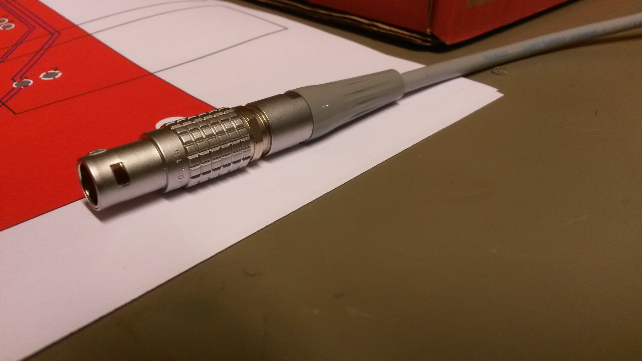
A commonly heard brand in the automotive- and racing branch when it comes to connectors is LEMO, which is known for its innovative push-pull system. This plug/connector design prevents plugs to be pulled from the cable or to easily vibrate loose. To disconnect the plug, it must be pulled by the grip of the plug, which releases the clamps that holds the plug in the connector. Not only is this a great feature to have on our motorcycle, it is also a very satisfying feeling when you click together your electrical systems.A fully assembled LEMO plug, including push-pull grip and bend relief. This assembly will deliver power to the Safety Control Unit.
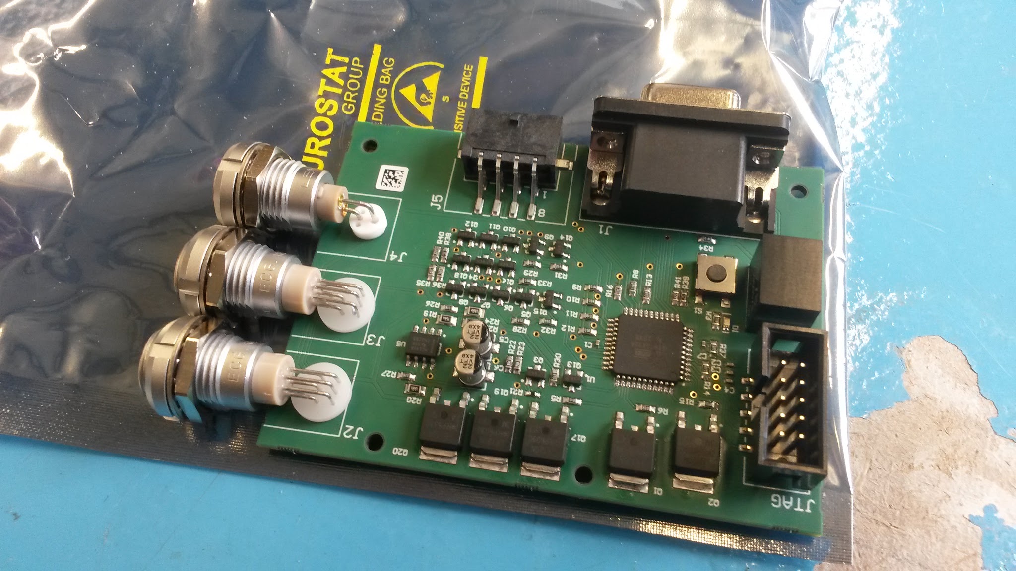
LEMO THT connectors visible on the right side of the Safety Control Unit. The connectors have a locking washer and nut to clamp them tightly onto the wall of a protecting casing.
Designing your cable tree
Of course there are situations where it’s more convenient to use other types of connectors. Usually because a component is manufactured with a specific type of connector, or because it is much easier to assemble or replace. Soldered connections are also prone to break with vibrations, this can be improved by applying a bit of glue. Crimping contacts are then a better alternative. Another thing that greatly improves a cable tree is consistency. Sometimes it is not totally clear, but if you can make some agreements on common connection types it helps a lot. For example on our motorcycle, all power delivering connections use female plugs, while power consuming connections use male plugs (similar to regular power plugs). Also always using pin 1 for 12V and pin 2 for GND prevents mistakes. In some cases where multiple similar connections need to be made, it is wise to use different types of plugs to make sure you never connect something in such a way that it breaks the equipment. For example, the fire extinguisher on our battery pack should never be able to be connected directly to its 9V battery, and the battery should never be able to be short circuited. Choosing these connections will prevent critical mistakes when connecting the 3 components:- Fire extinguisher: 1 male blade connector, 1 female blade connector
- 9V battery: 2 female blade connectors
- Thermal switch: 2 male blade connectors