The stack
Two months ago I wrote about the “stacks” in the battery pack. “Stack” has become often-used jargon within Nova Electric Racing for the building block of the battery pack. It contains a certain amount of battery cells connected in series, the BMS in order to monitor the health of the cells and structural support for the cells to keep them tightly in place. The latter is often done by using spot-welding or laser-welding, but last year it was done by soldering the cells onto a PCB. This provides a good electrical conductivity, but also puts a lot of heat from the soldering iron into the cells, which may damage them severely. It is also impossible to replace cells when doing this.
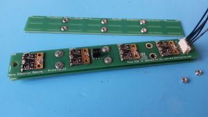
To solve both issues of soldering, we looked into the method of clamping, which is gaining popularity amongst pouch cell based designs, just like ours. In contrary to cylindrical cells, which have to be spot welded, pouch cells contain two thin copper tabs, a positive and negative terminal, which can be clamped between two materials. This method usually required more space, but by using the latest technology PCB components from Würth Elektronik it was possible to invent a clamping method that only requires some extra space in the length-direction of the cells. This extra space is occupied by an additional PCB to clamp the cell tabs beneath.

The latest stack prototype. Thanks to Eurocircuits and their short delivery time we were able to do some quick prototyping with this innovative design.
The major concern of clamping solutions is the possibly increased internal resistance of the stack and in the end also of the battery pack. Before assembling, some measures have to be taken to make sure the contact resistance of the cell tabs with the copper busbars is as low as possible. These measures are sanding of the cell tabs and the copper to remove any oxidation, which has a high resistance, and degreasing the cell tabs and the copper to remove any grease, which is not very conductive either.
The next step in the design process is to calculate the power losses of the battery pack due to the internal resistance. Measuring this resistance is not just a matter of using the resistance measurement function of a multimeter. This is because the resistance is very small, in the order of a few milliohms, and in the second place because a multimeter does not work when there already is a voltage applied on the device under test, which is the case for the battery cells.
However, the solution is not very difficult either. If we can flow a current through the stack, a voltage drop will be seen, just as with a resistor. Now drawing a current is exactly what the stack is designed for, so this is not very difficult. By using a programmable DC load it is possible to control the drawn current very accurately and indeed, when the load is enabled, it is observed that the total voltage on the terminals of the stack drops slightly. Using the well-known Ohm’s law, the internal resistance of the stack is the voltage drop divided by the drawn current. The linearity of this equation even allows to extrapolate the obtained resistance to the complete battery pack.
After we carried out these measurements and calculations, in total the estimated efficiency of our battery pack is 97% when full to 96% when the battery is low! With this positive prospect in mind, it feels great to continue with this design and implement it in our motorcycle.
